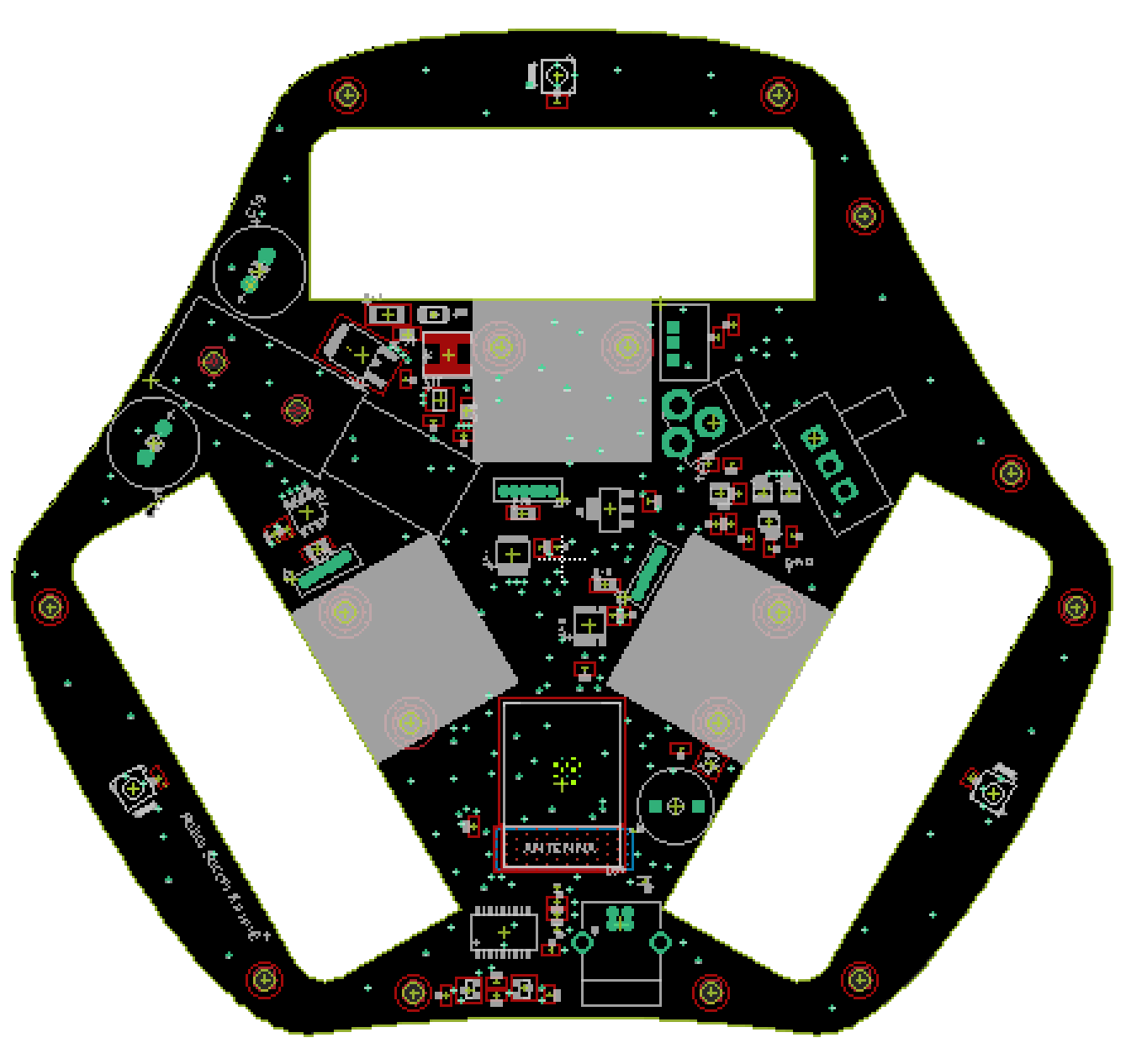
The robots board files can can be found on the GitHub project, current revision is rev2. This board is also the base support frame for the robots.
Links
Firmware
Robot’s firmware can be found in the firmware/ directory of the GitHub repository.
You first need to install PlatformIO, that is used to bring you the full build chain, along with the tools required to flash the robot. Simply run:
pio run
In the firmware/ directory to start the build. And:
pio run -t upload
To start uploading your firmware on the robot (via USB).
Commented design
ESP32 & Bluetooth
Robots are based on ESP32-WROOM-32E-N8 micro-controller, featuring 270Mhz dual-core with 32bit registers, integrated
Bluetooth and WiFi controller.
An USB to UART adapter is used (namely FT232RL-REEL) to allow direct USB communication for the robot, making it
possible to flash the on-board firmware without additional hardware. An USB type B connector was chosen because it
is robust (in the case you want to do some tests with the robot on the floor and the USB cable plugged).

Power
Robots are designed to be powered by a 2-cells lithium ion battery, through the on-board Jack 2.35mm barrel connector.
To avoid short-circuits or battery under-discharge, the board features a S-8252AAL-M6T1U battery protection IC.
When the battery voltage drops too low, the robot will first blink red and start beeping (which is the behaviour from its firmware), and eventually the BMS will cut the power.
In case of shortcut, the BMS will cut the power as well, you’ll have to turn the robot off and on again to get it restarting.

Buzzer
The buzzer is controlled by the micro-controller through an NPN transistor:

Leds
The board features 6 RGB LEDs (3 on the top and 3 on the bottom) that can be controlled individually.
They are sold under the name COM-16346 or WS2812B.
Only one wire is necessary to control them all. The FastLED library is used for that purpose.

H bridges
Robots features TB67H450FNG,EL all-in-one motor drivers. Those IC come with integrated mosfets, mosfet drivers and
current limiting features offering another protection against short-circuits.

Booster (Kicker)
To kick, the voltage is elevated to 20V using a MT3608 step-up converter. Two 25V 2200µF are then loaded, through a
270 ohm resistor to limit the current rush.
The kick consist in releasing all the current in a solenoid through a power

 Robot Soccer Kit
